Deepwater Element & Architect.

Mass transport debris and deepwater fans - architectural configuration

The 'architectural-element' approach provides a systematic means for describing sedimentary systems, organizing observations and measurements for diverse settings. It is becoming common to use this scheme for the description and classification of complex deepwater systems (Sprague et al, 2001). Just as with fluvial systems (Allen 1983; Miall 1985), the different types of depositional units and/or architectural elements common to deepwater sedimentary settings include lithofacies assemblages and their geometries, vertical profiles, and other internal and external characteristics that occur repeatedly and are often predictably (Sprague et al., 2002). It is argued that when deepwater reservoir architecture is understood this can be used to improve deepwater reservoir production performance (Hampton et al., 2006).


Sprague et al (2002) relate the hierarchy of “architectural elements" and their boundaries directly to the hierarchy of "stratal units" of sequence stratigraphy. Collectively these genetically related stratigraphic building blocks form the sedimentary architecture of the deepwater depositional system. This hierarchical framework of the units is based solely on the physical stratigraphy of the strata and their thickness is time independent. The elements show a progressive increase in scale from the deposit of a single sediment gravity flow (bed) to the accumulated deposits that comprise entire slope or basin floor successions (complex system set). When integrated with biostratigraphic data they provide part of the framework from which cycles of base level rise and fall may be interpreted. This approach enables the classification and eventually interpretation of these sedimentary Rocks and the prediction of their lateral extent as a three-dimensional architecture across the basin.

The interpretation of deepwater systems involving elements often mixes a top-down and bottom up approach to the hierarchies of the classification. The top-down system first establishes the gross depositional relationships of the deepwater sediments including the basic geomorphology of the depositional basin and the sea floor topography in the vicinity of the deepwater sediment accumulation. Then this is sub-divided into the main and general architectural elements of the deepwater fan that are traced and described from the sediment source to seaward in terms of their depositional dimensions. These are based on bounding surfaces, and the gross facies geometries and composition so neophytes and specialists alike find it easy to identify, understand and map them. These in order of decreasing complexity include:

  • basin margin slope, base of slope and basin floor
  • fan complexes
  • canyons & feeder channels
  • vevees, overbank sheets and drapes
  • mounds & lobes
  • contourites

 Click for large image


Principal architectural elements of deepwater systems considered on this page and in the site.

Concurrently detail is added by using a bottom-up classification that involves the relative abundaformnce of specific facies and the distribution of their depositional geometries. Different depositional sites will have similar facies characteristics, including sediment type, geometry and biostratigraphy. These can themselves be grouped into grosser sediment bodies and geometries that are broadly similar, and form the basis for the bottom-up approach to development of the classification. This high level hierarchy is made up of:

  • Channels
  • Sheets
  • Levees involving canyon fill
  • Leveed channel sands
  • Overbank areas
  • amalgamated channel sands
  • Amalgamated and layered sheet sands
  • Slumps
  • Debris flows
  • Marine shales

These combined heterogeneous facies, and their geometric character form the architectures of deepwater sediments that often have hierarchies unique to that local setting. These reflect differences in rates of sediment accumulation tied to geographic position within the fan systems; for instance the branches of a distributary systems or upslope in the feeder canyons. Measuring the horizontal and vertical dimensions of the various sediment bodies enables the comparison of these different settings.

Possamentier and Allen, 1999 and Csato and Kendall, 2001 have shown that the products of different subsidence/uplift histories within the same basin can lead to a relative sea-level lowstand on one basin margin segment while penecontemporaneously a relative sea-level rise may have been occurred an adjacent segment of the margin. From the perspective of defining reservoir geometries differences that occur in the character of the margin supplying a deep-water basin mean that locally higher but varying rates of sediment accumulation may collectively form packages of reservoir and seal or intra-reservoir facies particularly if there were variations in the local source parameters.
basin margin slope, base of slope and basin floor

Fan Complex Morphology
Traced from upslope into the basin both modern and ancient deepwater fan may be divided into the following end members of Beaubouef et al., (1999) namely:

The characteristic lithofacies and geometries of each of these geomorphic features overlaps with the adjacent members and this classification is very general. It is one way to approach these architectural members and others favor differentiating modern from the ancient deepwater fans on the basis that modern settings of the surface of the fan can be viewed in its entirety though its internal fabric is often inferred whereas for the ancient fan cross sections are visible in outcrops, wells and seismic cross sections while the fan surface is inferred. In the case of the ancient the distal to proximal positions would then be expressed vertically (Stelting et al., 2000).

Using the terminology of Stelting et al (2000) the geomorphology and facies associations associated with fine-grained, mud-rich turbidite fan systems of unconfined basins may be subdivided into:

  • Upper/inner or proximal fan region - expressed by an erosive canyon that down dip towards the middle fan becomes an erosional/constructional channel complex ('fan valley')
  • Middle fan - aggradational and characterized by a channel-levee complex that starts at or near the base-of-slope. This complex is typically sinuous and decreases in size upward and in a down channel direction (Peakall et al., 2000)
  • Outer/lower or distal fan - surfaced by small, ephemeral channels (distributaries) that grade downdip to sheet-sand complexes that mark the distal portion of the fan lobe.


In the constricted salt province of the Gulf of Mexico and on the west Africa continental slopes sheet sand and channel-levee systems are vertically inter-layered. This is caused by changes in the gradient of micro-basins or the locally scoured and or uplifted basin surface and fluctuating rates of sediment supply as the basin fills and sediment spills into the next basin downslope. The four elements that fill the confined basins are: leveed channel sands; amalgamated channel sands; amalgamated and layered sheet sands; and slumps, debris flows, and marine shales (Steffens, 1993).


Channels (including amalgamated channel sands)
Channels tend to have sharp erosional bases and updip their fill tends to be confined within the depression they erode into the sea floor. In canyons and valleys in the mid slope the proximal fill of these channels are often nested together, and may be amalgamated, or even be massive. Down dip the fill may spread beyond the confines of the channel margin and depending on the character of the sedimentary slope and source area the sands are less likely to be amalgamated and may be inter-Bedded with finer sediment. At the base of slope where channels debouch from canyons and valleys in the slope channel widths may range from greater than 3 km to less than 200 m (Posamentier & Kolla, 2003). As the channel meanders move down-system their sinuosity changes locally from moderate to high. The high amplitude reflection character common to these features is interpreted to record the presence of sand filling the channels (Posamentier & Kolla, 2003). Channel areas are generally elongate down dip. In cross sectional seismic strike profiles the channels just seaward of the canyon mouth show a characteristic "gull wing" shape formed by proximal levee deposits. Channels confined by erosion often occur in the mid fan to distal areas of the base of shelf margin slope. In the distal portions of the fan channels are not as deeply incised as they are up dip and more widely spaced and grade downdip into sheet-sand complexes that mark the distal portion of the fan lobe. As one proceeds down dip amalgamated turbidite sheets may become less common. Channel widths range from greater than 3 km to less than 200 m. Sinuosity ranges from moderate to high, and channel meanders in most instances migrate down-system. The high amplitude reflection character that commonly characterizes these features suggests the presence of sand within the channels.


Sheet Sands (including amalgamated and layered sheet sands)
The distal portions of deepwater turbidite fans are often the sites of the deposition of sheet sands. Posamentier and Kolla (2003) explain how low-sinuosity distributary-channel complexes form lobate sheets up to 5–10 km wide and tens of kilometers long that extend to the distal edges of these systems. These frontal splays or low-sinuosity, distributary-channel complexes are usually fed by high-sinuosity channels. These sheet-like sandstone units often consist of shallow channelized and associated sand-rich overbank deposits where levee thickness can no longer be resolved seismically (Posamentier and Kolla, 2003). When the deep-water turbidite sheets are deposited in unconfined basins these will vary in lithology, and geometry, reflecting that they are not axially confined by the basin. However they will tend to exhibit distinct vertical changes in facies that suggests these flows may have accumulated over small areas of the fan. These sheets will often be interBedded with laterally continuous shales that separate the sands.


In the case of confined small basins the sheets will lack a lateral change in the character of the component facies, will fine up and be vertically-stacked. These may be spread as layered amalgamated intervals that extend across an entire fan or even across the basin.

Leveed channel sands

Modern sea floor morphology show levee-overbank deposits accumulate lateral to the main channels of deepwater fans, especially on the outer channel bends. They lack the coarser character of the channel lag. Posamentier and Kolla (2003) record how locally levee deposits form sediment waves that reach heights of 20 m with spacings of 2–3 km. They show how the crests of these sediment waves are oriented normal to the inferred transport direction of turbidity flows, and how the waves have migrated in an up-flow direction. 


Sedimentary character of external and internal levees (Kane and Hodgson, 2010)

However, as Kane and Hodgson (2010) note, it is uncommon to identify outcrop analogues of channel-levees, and particularly they find a lack of identifiable internal and external levees. Howver they have found large-scale external levees enveloping channel systems whilst smaller scale internal levees bound individual thalweg channels within the channel-belt. They find this associated with two exhumed channel-levee systems from the Rosario Fm. of Baja California, and the Fort Brown Fm. of South Africa.

Channel-margin levee thickness decreases systematically down-system. They often show a lateral continuity in the facies of the proximal portions of levee facies, but there are often abrupt changes in the lithologies where channel fill and levee sands have an eroded contacts. Conceptual models based on outcrops, borehole images and seismic correlations help with identification of potential reservoir facies (Slatt, 2000).

Slatt et al (2004) record how levees deposits show difference in character related to their proximal to distal position across the levee. proximal levees will tend to have higher net sands, but tend to be thin Bedded with cut and fill features, mud-lined scours, climbing ripples, good connectivity and high angle and variable dipping Beds. The distal levee has lower net sand, thin Bedded, interBedded sand and silt, good continuity, and low angle ripple and the beds dip in a uniformly. The channel margins of levees are more complex, due to slumping. Channel margins are discontinuous, mud-lined, and have variable fluid communication in channel levee reservoirs. The breaching of levees, commonly at channel bends lead to the formation of crevasse-splay complexes. Posamentier and Kolla (2003) record how these features are similar to frontal splays, but smaller in size and commonly are formed by sheet-like turbidites. Channel levee and overbank examples from the Gulf of Mexico exhibit variable oil-water contacts across the reservoir.

Overbank areas


Slumps
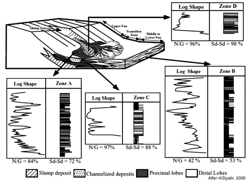
Where ever the slope of a basin margin becomes too steep to support the load of the sediment that is accumulating there, slumping of sedimentary material occurs. This can happen on unprecedented scales, as for instance in the Beaufort Sea and the submarine margin of the Nile Delta. Sediment that collected on the over-steepened upper and lower slope is commonly deformed by creep or more rapid downslope movement. Evidence of this movement is expressed in the intra-formational deformation of the sediment or sometimes by huge slump scars. Slumping is also common in mini basins connected and dissected by submarine canyons and valleys. As the channels downcut into the margins and floors of these basins, their margins oversteepen and fail, depositing slumped material over the sheet sands that form the overbank fill marginal to the channels.


Debris flows (link to further details)
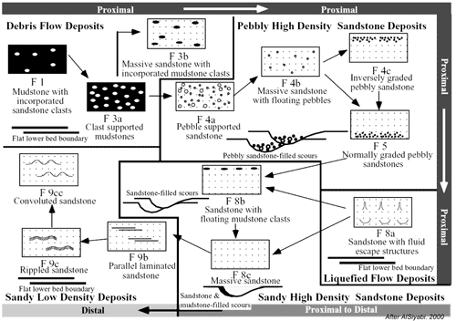
Debris-flow deposits form many of the same features of that turbidite sands express. These range from low-sinuosity channel fills, narrow elongate lobes, and sheets and are characterized seismically by contorted, chaotic, low-amplitude reflection patterns (Posamentier and Kolla, 2003). These deposits commonly accumualte on striated or grooved pavements that can be up to tens of kilometers long, 15 m deep, and 25 m wide. Posamentier and Kolla (2003) indicate that where the flows are unconfined, divergent striation patterns probaby reflect the flow direction and behaviour. Debris- flow deposits can extend at least as far basinward as turbidites, and individual debris-flow units can reach 80 m in thickness and commonly are marked by steep edges (Posamentier and Kolla, 2003). Transparent to chaotic seismic reflection character suggest that these deposits are mud-rich.

Marine shales
see section on deepwater sediments

Surfaces
Allen (1983) established, using fluviatile sediments as an example, that there at least four kinds of boundaries: concordant non-erosional (normal Bedding) ; discorcordant non-erosional ; concordant erosional; and disconcordant erosional contacts.

Click on highlighted Deepwater Gallery for access to a complete index to images, maps, diagrams and photographs of deepwater geology including the geology of Co Clare or access this gallery using the pull down menu on the header bar above.

References Cited
Allen, J. R. L. 1983, "Studies in fluviatile sedimentation: bars, bar complexes and sandstone sheets (low sinuosity braided streams) in the Brownstonews (L. Devonian), Welsh Borders". Sedimentary Geology, 33, 237-293.
Al-Siyabi, H. A., 2000, Anatomy of a type II turbidite depositional system: Upper Jackfork Group, Degray Lake area, Arkansas, in A. H. Bouma and C. G. Stone, eds., Fine-grained turbidite systems, AAPG Memoir 72/SEPM Special Publication 68, p. 245–262.
Beaubouef, R.T., Rossen, C., Zelt, F., Sullivan, M.D., Mohrig, D., and Jennette, D.C., 2000, Deep-water sandstones, Brushy Canyon formation West Texas: Field Guide for AAPG Hedberg Field Research Conference, April 15-20, 1999, AAPG Continuing Education Course Note Series #40, 48p.
Csato, I., C. G. St. C. Kendall, 2001, "Modeling of stratigraphic architectural patterns in extensional settings – Toward a conceptual model", Computers and Geosciences.
DeVay, J. C., D. Risch, E. Scott, C. Thomas, 2000, A Mississippi-sourced, middle miocene (M4), finegrained abyssal plain fan comples, northeastern Gulf of Mexico, in A. H. Bouma and C. G. Stone, eds., Fine-grained turbidite systems, AAPG Memoir 72/SEPM Special Publication 68, p. 109–118.
Gardner M.H. and J.M. Borer, 2000, Submarine Channel Architecture Along a Slope to basin Profile, Brushy Canyon formation, West Texas, in Fine-Grained turbidite Systems/edited by A. H. Bouma and C. G. Stone. AAPG Memoir 72, SEPM Special Publication No. 68., p195-214
Hampton, Bret D., Thomas V. Wilson, and Robert Crookbain, 2006, “From Euphoria to Reality: One Operator's Experience with Reservoir Performance in the Deepwater Gulf of Mexico” Connectivity and Performance of Deepwater Reservoirs (SEPM), AAPG Annual Convention, April 9-12, 2006 Technical Program
Kane IA, and Hodgson DM, 2011, Sedimentological criteria to differentiate submarine channel levee subenvironments: exhumed examples from the Rosario Fm. (Upper Cretaceous) of Baja California, Mexico, and the Fort Brown Fm. (Permian), Karoo Basin, S. Africa. Marine and Petroleum Geology vol 28 pp 807-823
Miall, A.D., 1985, Architectural-element analysis: A new method of facies analysis applied to fluvial deposits: Earth-Science Reviews, v. 22, p. 261–308
Peakall, J., W. D. McCaffrey, B. C. Kneller, C. E. Stelting, T. R. McHargue, and W. J. Schweller, 2000, A process model for the evolution of submarine fan channels: implications for sedimentary architecture, in A. H. Bouma and C. G. Stone, eds., Fine-grained turbidite systems, AAPG Memoir 72 /SEPM Special Publication 68, p. 73–88
Posamentier, H.W., Allen, G.P., 1999,. Siliciclastic sequence stratigraphy: concepts and applications. SEPM Concepts in Sedimentology and Paleontology no. 7, 210 p.
Posamentier, Henry W. & Venkatarathnan Kolla, 2003, "Seismic Geomorphology and stratigraphy of depositional elements in Deep-Water Settings", Journal Sedimentary Research, Vol. 73, No. 3, P. 367–388
Slatt, R.M., 2000, Why outcrop characterization of turbidite systems?, in Bouma, A.H., C. Stelting, and C.G. Stone (eds.), Fine-grained turbidite systems, Amer. Assoc. Petrol. Geol. Mem. 72/Soc. Sediment. Geology Spec. Publ. 68, p. 181-186
Slatt, Roger, James Forgotson, Jr., and Azzeldeen A. Saleh 2004, Petroleum geology of the the deepwateer Jackfork Group and Atoka formation with a primer on the petrokeum geology of deepwater depositionla systems, http://www.pttc.org/solutions/sol_2004/539.pdf
Sprague,A. R., P. E. Patterson, R.E. Hill, C.R. Jones, K. M. Campion, J.C. Van Wagoner, M. D. Sullivan, D.K. Larue, H.R. Feldman, T.M. Demko, R.W. Wellner, J.K. Geslin1 (2002), "The Physical stratigraphy of Fluvial strata: A Hierarchical Approach to the Analysis of Genetically Related Stratigraphic Elements for Improved Reservoir Prediction", (Abstract) AAPG Annual Meeting
Steffens, G. S., 1993, Gulf of Mexico deepwater seismic stratigraphy: AAPG Annual Convention Official Program, p. 186.
Stelting, C.E., A.H. Bouma, and C.G. Stone, 2000, Fine-Grained turbidite Systems: Overview, in Fine-Grained turbidite Systems/edited by A. H. Bouma and C. G. Stone. AAPG Memoir 72, SEPM Special Publication No. 68., p1-8
Stow, D.A.V., 1994. "Deep-sea processes of sediment transport and deposition. In: Sediment Transport and Depositional Processes", ed. by K. Pye, Blackwell Sci. Publ. pp 257-293
Stow, Dorrik A.V. and Mayall, Mike, 2000, "Deep-water sedimentary systems: New models for the 21st century", Marine and Petroleum Geology 17, 125-135
Stow, D.A.V. and Mayall, M., editors, 2000. "Deep-water Sedimentary Systems: Thematic Set", Marine and Petroleum Geology, Volume 17, No. 2.
Sprague, A.R.G., Garfield, T.R., Goulding, F.J., Beaubouef, R.T., Sullivan, M.D., Rossen, C., Campion, K.M., Sickafoose, D.K., Abreu, V., Schellpeper, M.E., Jensen, G.N., Jennette, D.C., Pirmez, C., Dixon, B.T., Ying, D., Ardill, J., Mohrig, D.C., Porter, M.L., Farrell, M.E., Mellere, D., 2005. "Integrated Slope Channel Depositional Models: The Key to Successful Prediction of Reservoir Presence and Quality in Offshore West Africa"; CIPM, cuarto EExitep 2005, February 20-23, 2005, Veracruz, Mexico, 1e13 pp.

Sunday, February 24, 2013
Tulsa Web Design    Tulsa Graphic Design     Tulsa SEO    Tulsa Search Engine Optimization